When you’re new to modular synthesizers, it’s all too easy to fall into the rut of just recreating the patches hardwired into your existing synths. But don’t forget that one of the main reasons to go modular in the first place is to get out of those ruts and explore new sonic and creative territory.
The video below is the result of a tech failure (a new module that was wired incorrectly) that jerked me out of a similar rut I had fallen into recently. The main problem was that a filter’s control voltage inputs were inverted: when the incoming voltage went up, the filter’s cutoff frequency went down instead. (Its resonance knob was also wired backwards.) After some initial confusion, this led to a productive hour-long session trying out some non-standard ideas, such as:
- inverting the oscillator control voltage and sending it to the filter cutoff, creating a syncopated pattern where the low pass filter closed down on the high notes and opened up on the low notes
- using inverted envelopes with a high pass filter, to get a satisfying full-spectrum pluck on the attack of the note that decayed to a thinner, brighter sound (instead of the typical “pee-chewwwww” sound you get with a normal envelope feeding the cutoff of a high pas filter)
- using full resonance instead of little or none as a starting point when setting the filter cutoff for a new patch
The first idea (as well as a little bit of the third) is explored in the video below. I also spent some time playing with gate durations that were longer than an individual step in the sequence, resulting in a form of clock divider that caused the ADSR to trigger on every other note – or even non-powers-of-two time divisions of the master clock:
If I had to name two main takeaways from this video, they’d be to 1) make sure you have utility processor modules like voltage offset/scale/invert/mixers (here’s a few ideas) plus clock multipliers/dividers, and 2) to insert them into the middle of your “normal” modulation or gate signal paths to encourage experimentation with ideas you wouldn’t normally explore.
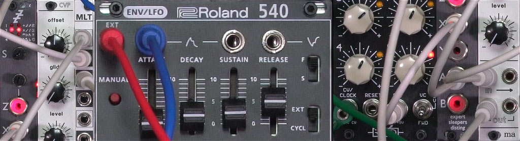
For those trying to reverse-engineer the patches I used, as with my other videos I color-code my patch cables as follows:

Very useful information. I consider myself well versed in the old school Moogs and Emus, but I am quite the noob on Euro racks, as they have introduced many new modules than existed back-in-the-day. I am slowly adding Euro modules — which, so far, interact very well with my Dot-Com 5U P22 — to my set up, to expand the sonic possibilities. So far, just a few modules, but more are on my “must buy” list. These tutorials have been useful, and I look forward to seeing future videos.
Inspiring. Thx. Started with modular this year. Now I have an almost full 6U case. I’m waiting for a second mixer, then it’s full… I have chosen analog classic modules. Nothing fancy. No mega-multi-function modules. Think I have come to the evaluation step in my modular development. I have some expansion plans but they can wait. (Confession I have two rompler drum modules and a reverb. Saves space in the case but not very analog…)