I’ve been playing around with a simple extension to the typical synthesizer voice patch that has been producing some interesting results.
The short version is: Replace the typical oscillator or waveform mixer with a crossfader. Then try using all sorts of different modulation sources for the crossfade, from simple LFOs and envelopes to audio-rate crossfades using a third waveform or oscillator. Then, extend the idea to LFOs and other modulation sources, as well.
The video below is a demo I gave to a New Mexico Control Voltage modular meetup featuring some of my VCO crossfading experiments. After that, I’ll explain the patches for those experiments in more detail, and suggest some other ideas to try.
Starting Simple
This technique uses the oscillators, VCAs, LFOs, etc. you already have, but you may need to add one more module: a crossfader. I’ve been using the Happy Nerding Dual Xfade: it’s a dual unit in just 4 hp, has an attenuverter and initial bias for the crossfade CV. However, many other crossfader modules should work as well. In general, the analog crossfaders I’ve tried have no problem being used at audio rates, while some digital ones can start to act odd at those rates.
To start, patch two VCOs – or two waveforms from the same VCO – into the crossfader’s two inputs, which are often labeled A and B. We’ll call these our source waveforms. A few VCOs have waveshaping built in (such as between a triangle and sawtooth), which is a variation of the core idea. An excellent example is the SSF Zero Point Oscillator.
Use the manual crossfade position control available on most crossfader modules (or the initial waveshape setting on a shape-morphing VCO) to set the initial mix between the two sources. Then patch the output of the crossfader into the rest of your normal voice chain, such as to a VCF or a wave folder:

Now let’s animate that mix. A typical crossfader accepts a ±5v CV input, with -5v being 100% of the A input, and +5v being 100% of B. Fortunately, most LFOs output those levels, so center the crossfader’s initial position (50% each of A and B), and patch the LFO into the CV input for the fade:
As a starting point, tweak the attenuator on this CV input until the output just touches 100% of A or B at the extremes of the LFO’s waveform. Increasing the CV amount beyond this threshold will create “holds” at full A or full B; reducing the fade CV’s modulation depth will make sure that a bit of both A and B are always present in the output.
Now try an envelope generator patched into the fade CV input. A typical EG will go from 0 to +5, +8, or +10 volts. This will need some tweaking to get a full range of movement from A to B and back again. For example, start with the crossfader’s initial fade knob at full A; the envelope will then fade to B and back to A. If you like, you can set an initial crossfade offset so there’s always some “B” mixed in at the start and end of a note. The sustain level of the envelope sets the A/B mix while the envelope’s gate level is high. If you want to fade in the opposite direction, invert the envelope, and change the initial crossfade as needed (i.e. full B to start).
If your envelope is not giving you a deep enough A/B crossfade sweep (probably because its voltage range is under 0-10v), boost the envelope’s modulation depth with a utility mixer that can increase its level (more and more can that these days; I like the Frap Tools 321). If your utility mixer only attenuates the level of signals with no boost, split the output of the envelope generator and patch it into two inputs of the mixer; then take the sum of those inputs as your output. Set one input level to 100%, and then add in the second level as needed:
You can try other modulation sources for the crossfader, such as a smooth random voltage generator, or a sample & hold that might be triggered at the start of every note. You can also try performance controls such as a mod wheel, velocity, aftertouch, or an extra channel from your sequencer to control the crossfade – this will allow each note to sound different, such as plucking a string at different positions along its length, or striking a drum in different locations.
Audio Rate Crossfading
The simple starting points suggested above will give you some timbral movement in your notes compared to a normal, static oscillator or waveform mixer. But the real fun starts when you modulate the crossfade at audio rates, using another waveform output or an additional VCO.
In this case, you would patch separate source waveforms into the A and B inputs, as well as into the crossfade control voltage input. We’ll call this third connection the crossfade waveform; I chose the pulse wave in the diagram below:
The output will contain harmonics from at least all three of those sources, and probably more. If the crossfade control waveform also happens to have a sudden jump in level – such as a sawtooth or pulse wave – this will most likely cause a sudden jump in level as you switch from input A to B (or back), as their individual waveforms will probably not line up at this switch point:
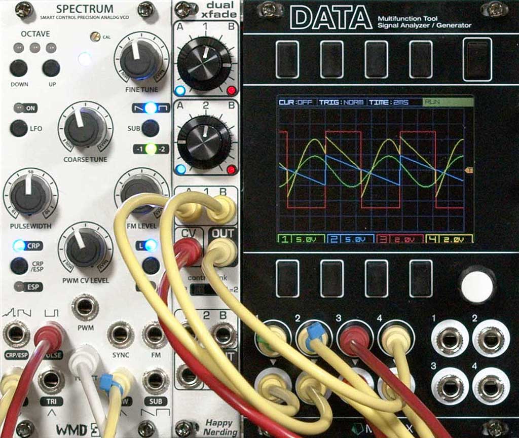
If all three waveforms come from the same oscillator (as in the image above) – or from different oscillators that have been synchronized – the output will be a static, unchanging timbre. It will be more interesting than any one of its components – and probably more interesting than a normal mix of the components – but it will still be static. Things get far more interesting if you can introduce changes in any of the component waveforms.
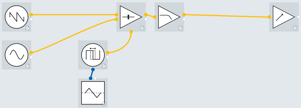
For example, say you used a pulse wave for the crossfade CV, as shown above. You could use an LFO, envelope generator, or other modulator to vary the width of this pulse:
Modulating the width of the pulse not only animates the harmonic mix, but also moves the sudden discontinuous jump between the A and B source waveforms, resulting in a sound somewhere between pulse width modulation and hard sync. This is the idea behind “wave splicing” oscillators such as the Dove Audio WTF (Window Transform Function) Module, the Future Sounds Systems OSC2 Recombination Engine, and the MOK Waverazor.
Life gets more interesting if you change the tuning of the three component waveforms. Just using three separate oscillators tuned to the same pitch will probably exhibit subtle phasing between them, resulting in the harmonics fading in and out without the need for additional modulation. Tuning the components to different octaves introduces even more interest and a wider range of harmonics.
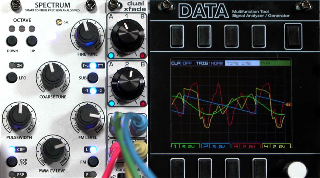
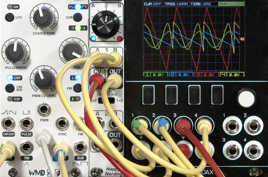
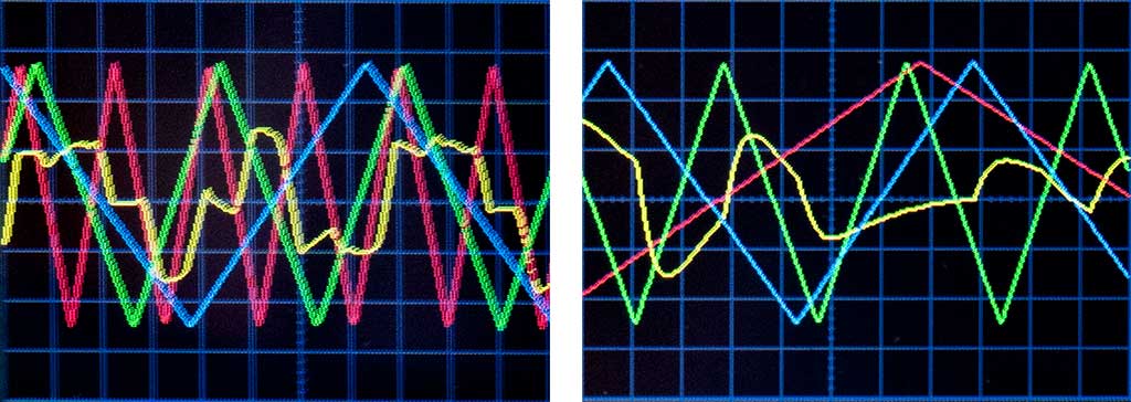
The image on the left below shows the result (yellow) of tuning waveform B (blue) a few octaves higher than waveform A (green) and the CV source (red); the image on the right shows what happens when the oscillator oscillator is tuned to one octave higher than the A and B source oscillators:
The oscillators can also be tuned to different intervals, such as fourth and fifths. Using a suboctave output as source waveform A or B also usually produces a rich sound.
As noted above, using a pulse wave to perform the crossfade (the normal wave splice approach) will produce a lot of buzzy high harmonics, thanks to the discontinuities that occur between source waveforms A and B at the point the crossfade oscillator suddenly changes levels.
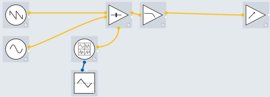
To create a smoother composite sound with fewer high harmonics but still a lot of rich movement in the middle harmonics, use a waveform other than a pulse to perform the crossfade. For example, this is what happens when you use a triangle wave to drive the crossfade between a sine wave and a sawtooth:
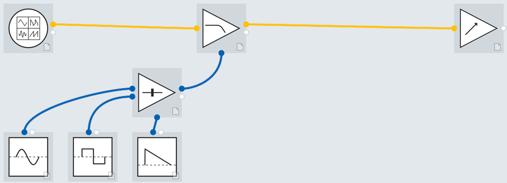
It’s even better if you can modulate the shape of this crossfade wave, just as you could the pulse width. In my video examples above and below, I used one the VCO algorithms in the Expert Sleepers Disting that morphs between sawtooth and triangle waves. If your crossfade VCO does not allow voltage controlled waveshaping, you can try patching your chosen crossfade waveform through a waveshaper module such as a wave folder, and then modulate that.
The last few minutes of the video above demonstrates scanning between waveshapes in a digital wavetable oscillator to drive the crossfade; the effect can be quite complex, including vocal-ish sounds. That patch and resulting waveforms is shown below:
Improving LFO Waveforms
Happy with how this crossfading technique has breathed new life into my oscillator waveforms, I have started to experiment with using it for LFO waveforms as well.
I personally have become bored with the predictable, repetitive nature of the typical LFO shapes, including the triangle wave. This has led me to explore chaos based modulators as well as other smooth random modulation sources. But a crossfader and a few LFO waveshapes – or even better, multiple LFOs with independent rates – can create their own exotic, morphing waveshapes.
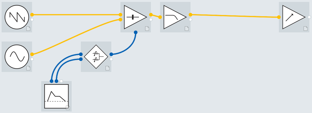
As suggested above, you can try a variety of sources to crossfade between two different LFO waveshapes, including another LFO, an envelope generator, or performance controls such as aftertouch or a mod wheel. The patch below uses an Attack/Decay envelope generator to crossfade from one LFO to the other during the life of a note:
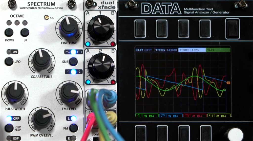
A popular LFO module is the DivKid/Instruō øchd, which includes eight triangles waves that each run at different yet connected rates. This is an excellent module to pair with a crossfader. In the oscilloscope traces below, I use two of the “middle” outputs of ōchd for the A and B shapes (the green and blue traces), and then use either a higher or lower output (the red trace) to crossfade between them. As you can see, the output (yellow) is very interesting:
The output of this can then be used to modulate anything you would normally drive with an LFO, such as pulse width, filter cutoff, a phase shifter or flanger, or even the crossfader for your VCO waveshapes.
The bottom line is: I want new waveshapes to play with, and I want more motion in my patches. This technique provides a relatively easy way to get those results, just by adding a crossfader to your existing modules.
Some Additional Background
This idea started when I watched Jon Sonnenberg present his idea for “wave replacement” (what I call wave splicing) at the 2018 Knobcon show. You can click here to see his original presentation, and here to see a supplementary video where he focus on an oscilloscope display of the output.
As I was watching that, two ideas popped into my head:
- why not use waveforms other than a pulse to perform the splicing?
- why not detune the oscillators, instead of synchronizing them together?
That second idea was based on a personal failure of sorts. When I first came up with the idea of Vector Synthesis, I too synchronized all four component oscillators together, focusing on just the changing waveshape that resulted from the two dimensional vector crossfade. Josh Jeffe – product manager of the Prophet VS – rightfully questioned this assumption I had made, as he missed the motion caused by the detuned chorusing and other possibilities offered by independently and freely tuning the component oscillators. Hats off to him for that extension to my original idea. (In my defense, I was also trying to minimize the hardware required to create the effect. But independently tuning the four component oscillators does sound a lot better.)
After seeing several wave splicing oscillators appear that all used hard, pulse-like splices between waveforms, I decided to finally patch up my idea of using other waveforms; that resulted in the video below:
Since then, I took a step back and realized the real idea worth pursuing is not just to provide “better” wave splicing, but instead the broader yet very simple idea of crossfading between waveshapes to create more interesting waveshapes. And that was the basis for this long post. Thank you for your patience in reading it; I hope you have fun patching it up, trying it yourself, and extending it beyond my original ideas here. Please use the comments below to share what you came up with!




Love this technique! I would like to add that Mutable Instruments Frames (or its clone Plancks) is an oft overlooked module that is excellent for this as it allows complex crossfading between four channels. I love patching in various FX (distortion/waveshaper/clouds…) and modulating the crossfading with a sequence from the Turing Machine.